-
 Photos: Transmitter and various sensor types
 -
-
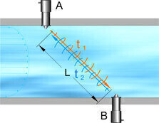 Figure: Schematic illustration of transit time difference principle
 -
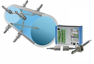
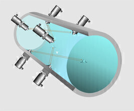 Photo: Schematic illustration of multiple measurement paths
 -
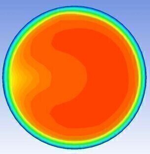 Photo: CFD-model of a disturbance (elbow)
 -
Photos: Transmitter and various sensor types
-


Water/wastewater
Flow Rate Measurement in full Pipes using the Transit Time Method
Jan 16 2017
Particularly in large diameters the relevance of water volume measurement is growing. The challenge with cooling water or fresh water processes is to generate accurate flow recordings or to document and to control individual consumptions and withdrawal quantities. Flow detection, however, particularly in large diameters is highly demanding. In such cases the transit time measurement thanks to its high flexibility as a reliable and cost-efficient measurement system is literally made for permanent flow metering.
Securing the Water Supply
The requirement for many processes is to feed as little fresh water as possible. Water feed and withdrawal volumes need to be monitored constantly as well. All these tasks require to permanently investigate and to verify flow rates. Integration into higher systems (such as SCADA systems) is indispensable since the systems are generally used within large areas.
Conception and Selecting the Measurement System
To ensure constant flow recording it is necessary to use a measurement system capable of determining the medium velocity covering the entire wetted area. This is important particularly with fluctuating flow conditions. Many measurement systems commonly used either feature spot velocity measurement only or do provide the required penetration depth. Quite simply, some measurement systems cause too much costs or require too many employees when it comes to installation. Measuring high medium velocities to many systems is an impossible task, too. A cost-efficient method to obtain reliable information on the prevailing discharge / flow is the measurement using the ultrasonic transit time difference principle. Such systems stand out for low maintenance expenses and high operational safety. They can be flexibly used with all needed sizes and media. Compared to other methods, the measurement system moreover has the advantage to be largely independent of the properties of the media to measure such as electrical conductivity, fluctuating temperatures or viscosity.
This measurement principle is based on directly measuring the transit time of an acoustic signal between two ultrasonic sensors. Such sensors are also described as hydro-acoustic converters (A and B in the illustration below). Two sonic impulses are transmitted successively after each other and the different transit times between transmitter and receiver are measured. The impulse heading downstream (t2) reaches the receiver sooner than the impulse heading upstream (t1).
The required times are measured by utilising highly accurate time measurements as well as a signal correlation. This signal correlation compares the transmitted signal with the signal received by the opposite converter. The comparison therefore enables to determine the accurate moments of transmission and reception of the measurement signal. The difference between both determined times is proportional to the average flow velocity within the measurement path.
Figure: Schematic illustration of transit time difference principle
|
t1= Impulse time against flow direction t2= Impulse time in flow direction L= Transit time / distance between sensors |
Formula: Average transit time difference in a measurement path
By using this formula it is possible to determine the average cross-sectional velocity and hence the flow rate from the measured average velocities within the individual layers related to the according velocity coefficients.
|
Q= flow rate k= measurement place-specific correction factor A= wetted area vg= average velocity |
Formula: General flow calculation
The more measurement paths are used, the more information on the flow profile prevailing at the measurement spot can be gained. The total flow rate in this case is the total of the individual flow rates. Using multiple measurement paths hence will increase the accuracy of the flow rate determination. Arranging the sensors of a multi-path measurement crosswise reduces the effects of disturbing flows crossing the main flow direction. Cross flows may cause measurement errors. Using a multi-path measurement setup may also reduce the length of intake and discharge sections required to calm down the flow profile at the measurement point.
Photo: Schematic illustration of multiple measurement paths
Thanks to novel CFD models (Computational Fluid Dynamics) and comprehensive testing at renowned institutes, influence and behaviour of flow profiles downstream of standard disturbances could be examined. Based on the results it is now possible to integrate flow profiles downstream of elbows and other disturbances into calculation models directly in the transmitter of the measurement system. Only the type of disturbance and the distance to the measurement spot need to be specified. From these specifications the measurement automatically determines the correction factors to use. The result of the flow measurement is therefore highly accurate and can be even used together with shorter calming and intake sections.
Photo: CFD-model of a disturbance (elbow)
The new NIVUS GmbH device types allow using the transit time method both as invasive measurement and clamp-on system. Here the type of sensor used must be selected depending on the situation on the measurement place. Highest measurement accuracy can be achieved by using a multi-path system with wetted sensors in a defined arrangement. If it is not possible to insert the sensor into the process (abrasive, corrosive or other problematic media), the sensors can be installed on the pipeline from the outside without process interruption (clamp-on measurement system).
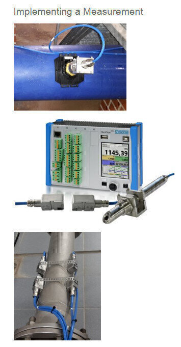
Implementing a Measurement
Photos: Transmitter and various sensor types
Tasks of the example depicted: long-term recording of flow rate and flow velocity for archiving in a distribution system operator’s drinking water supply pipeline.
Accuracy requirements in this case are very high since the measurement place is to be used for billing purposes. A NivuFlow 600 system with invasive sensors by NIVUS GmbH was used. The sensors were inserted into the pipe by using tapping nozzles. This is how the readings could be provided to the following SCADA system with the required level of accuracy via data connection. The variety of sensors and installation material allows picking up readings at various measurement spots.
A very minimalistic approach can be followed in terms of spare parts stock: no need to stock diameter-specific parts, one measurement system for almost all pipe diameters and measurement places.
Summary
Flow measurements based on the ultrasonic transit time difference principle have not only undergone many years of extensive testing. They have also proven successful in practical use and stand out for a high level of accuracy and flexibility in terms of applicability in various measurement places. Thanks to robustness and ease of maintenance the ultrasonic transit time principle is perfectly suitable for both measuring in pipes with smaller diameters (such as process water or cooling water) as well as for permanent measurements on demanding measurement sites (such as large pipe diameters, hydro-electric plants, high process water volumes and varying media). With new-generation devices, however, the benefits of the method have been significantly extended. Among other things, measurement ranges and accuracies of flow measurements have been increased considerably.
Find more Information about the flow measurement by means of Transit time method type NivuFlow 600
.jpg)


Digital Edition
IET 35.2 March
April 2025
Air Monitoring - Probe Sampling in Hazardous Areas Under Extreme Conditions - New, Game-Changing Sensor for Methane Emissions - Blue Sky Thinking: a 50-year Retrospective on Technological Prog...
View all digital editions


_(4427399123)-(2).jpg)


.jpg)

Events
May 06 2025 Nuremberg, Germany
May 10 2025 Karachi, Pakistan
May 11 2025 Vienna, Austria
May 11 2025 Seoul, South Korea
Salon Analyse Industrielle & Instrumentation
May 14 2025 Paris, France